The advancement of Advanced Driver-Assistance Systems (ADAS), autonomous vehicles, and industrial radar sensors is critically dependent on the performance of millimeter-wave (mmWave) radar printed circuit boards (PCBs). Operating at high frequencies of 24 GHz and 77 GHz, these PCBs demand exceptional electrical characteristics, precise manufacturing, and material stability. This article details the essential technical specifications and manufacturing considerations for high-performance mmWave radar PCBs, providing a foundational guideline for engineers and procurement specialists.
1. Critical Material Selection for High-Frequency Performance
"The choice of laminate is paramount in mmWave PCB design, as it directly impacts signal integrity and loss. Two primary high-performance material systems are recommended:
1、Rogers RO4835 with S1000-2 Prepreg: This hydrocarbon ceramic laminate is an excellent choice for its balanced performance. It offers a stable dielectric constant (Dk) of 3.48, low loss tangent, and reliability comparable to FR-4, making it a robust and cost-effective solution for many 77GHz applications.
2、Rogers RO3003G2 with ITEQ IT180 or Isola 370HR: For designs requiring the ultimate in electrical performance, a hybrid stack-up utilizing Rogers RO3003G2 ceramic-filled PTFE laminates is preferred. This material provides an exceptionally low and stable Dk of 3.00, minimizing signal propagation delay and loss. It is combined with ITEQ IT180 or the widely used Isola 370HR for the multilayer construction, providing a reliable and high-performance substrate."
2. PCB Construction and Electrical Parameters
"The physical construction of the PCB must be meticulously controlled to ensure consistent impedance and mechanical stability.
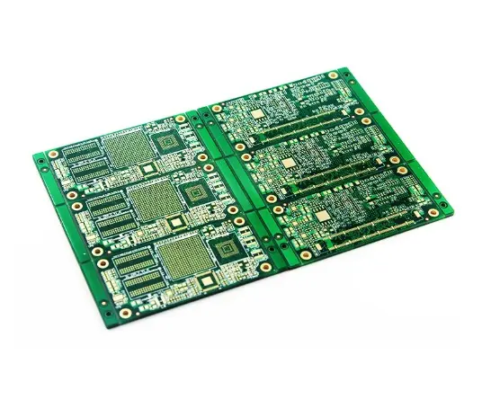
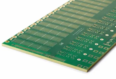
1、Layer Count: Configurations typically involve 6-layer or 8-layer stack-ups, providing sufficient grounding, power, and signal routing layers for complex radar system-on-chip (SoC) components.
2、Finished Board Thickness: A controlled thickness range of 1.0 mm to 2.0 mm is standard, balancing structural rigidity with the dimensional requirements of the end application.
3、Dielectric Constant (Dk): The specified Dk values of 3.48 (for RO4835) and 3.0 (for RO3003G2) are critical for accurate impedance calculation and controlled signal propagation at microwave frequencies."
3. Manufacturing Tolerances and Surface Finishes
"Precision manufacturing is non-negotiable for mmWave circuits. Key fabrication capabilities include:
1、Fine-Line Etching: Minimum trace width and spacing of 4 mil / 4 mil are essential for achieving controlled impedance transmission lines, such as microstrips and coplanar waveguides, at these bands.
2、Copper Thickness: Finished copper weights of 0.5 oz/ft² or 1.0 oz/ft² are standard, selected based on current-carrying capacity and the ability to etch fine features.
3、Through-Hole Treatment: To prevent solder wicking and ensure reliability, via plugging with epoxy resin is specified. This process fills the plated through-holes, creating a planar surface for component assembly."
4. Final Finishes and Identification
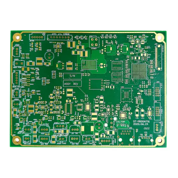
"1、Surface Finish: Electroless Nickel Immersion Gold (ENIG) is the highly recommended surface finish due to its flat surface (essential for fine-pitch components), excellent solderability, and long shelf life. Immersion Silver serves as a viable alternative for certain applications.
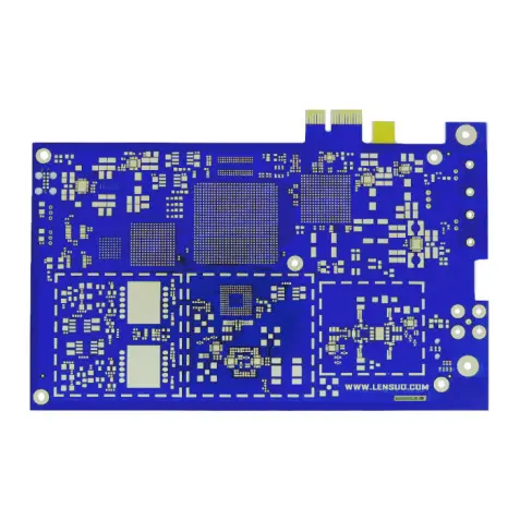
2、Solder Mask: Available in green, blue, or red, the solder mask must be applied thinly and uniformly to prevent affecting the impedance of exposed RF transmission lines."
Designing and manufacturing a reliable 77G/24G radar PCB requires a deep understanding of high-frequency materials and precision fabrication processes. Adhering to the specifications outlined above—from the selection of advanced laminates like Rogers RO4835 or RO3003G2 to controlling etch tolerances and via treatment—is crucial for achieving the desired performance in demanding automotive, industrial, and communications applications. Partnering with a PCB manufacturer experienced in mmWave technologies is essential for success.
General: Technology: Millimeter Wave Radar PCB
Model: 77G / 24G
Materials: Laminate: Rogers RO4835 laminates with S1000-2 prepreg
Alternative Laminate: Rogers RO3003G2 high-frequency laminate combined with ITEQ IT180 or Isola 370HR for the multilayer construction
Electrical Properties: Dielectric Constant (Dk): 3.48 / 3.0 (typical for specified materials)
Construction: Layer Count: 6-layer or 8-layer configuration
Finished Board Thickness: 1.0 mm to 2.0 mm
Conductivity: Copper Thickness (Finished): 0.5 oz/ft² or 1.0 oz/ft²
Physical Attributes: Solder Mask Color: Green, Blue, or Red
Fabrication Capability: Minimum Trace Width / Spacing: 4 mil / 4 mil
Surface Finishes: Final Surface Finish: Electroless Nickel Immersion Gold (ENIG) or Immersion Silver
Through-Hole Treatment: Via Capping/Filling (Resin Plug)

")