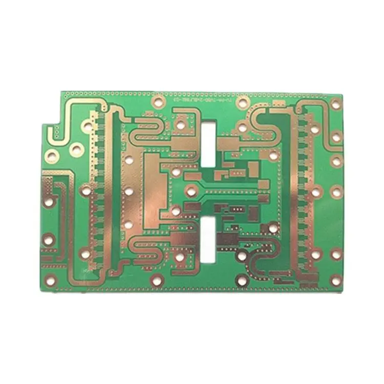
Microwave PCB
Microwave PCB Manufacturing Technical Parameters
1、Core Materials
Substrate Type: PTFE-based high-frequency materials (e.g., Rogers series), Ceramic-filled PTFE composites, Hydrocarbon-based (HBN) laminates
Dielectric constant: 2.2 to 10.0+ (selected based on design), Tolerance tightly controlled to ±0.05 or better
Tangent of the loss angle: Very low, typically in the range of 0.0009 (e.g., RT/duroid 5880) to 0.004
Thermal conductivity: High thermal conductivity required for some applications (e.g., Rogers TC series, >1.0 W/m/K)
2、Design & Structure
Impedance Control: Tightly controlled, typically ±5% or tighter (e.g., ±3%), modeled for microstrip, stripline, etc.
Trace Width/Space Tolerance: Very tight, typically ±0.02mm or better, to ensure consistent electrical performance
Lamination Registration Tolerance: Tightly controlled within ±0.05mm to prevent misalignment in multilayer boards
Surface Finish: Electroless Nickel Immersion Gold (ENIG), ENEPIG, Immersion Silver, OSP
3、Critical Manufacturing Processes
Hole Plating: High requirements for hole wall quality, using plating processes for high aspect ratios to ensure signal integrity at microwave frequencies
Pattern Etching: Tight control of undercut to ensure smooth trace edges and clean profiles, minimizing signal loss
Lamination Process: Precise control of pressure, temperature, and time to avoid material deformation and changes in dielectric properties
4、RF Performance
Insertion Loss: Required to be very low at target frequencies (e.g., 10GHz, 20GHz)
Phase Consistency: Phase difference between different paths in multi-channel systems must be tightly controlled
Quality Factor (Q-value): Required for circuits like resonators, demanding high-Q materials
See details