The Server Power Module is the heart of a data center's power system, converting and delivering clean, stable power to critical computing hardware. Its performance, efficiency, and reliability are fundamentally determined by the quality of its Printed Circuit Board (PCB). A poorly designed PCB can lead to power losses, thermal failures, and system instability. This article analyzes the key stages of creating a robust Server Power Module PCB, from the foundational stackup to selecting the right manufacturing partner.
1. PCB Stackup: The Critical Foundation
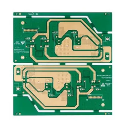
The PCB stackup is the architectural blueprint of the board. For a Server Power Module handling high currents and sensitive control signals, the stackup is not an afterthought—it is a primary design decision. A well-planned stackup ensures proper impedance control, minimizes electromagnetic interference (EMI), and enhances power integrity.
A typical multilayer board for this application might consist of:
Signal Layers: For control circuitry and feedback loops.
Power Planes: Thick copper layers (e.g., 2oz to 4oz) dedicated to high-current paths (like 12V, 5V). These planes provide low-impedance power distribution.
Ground Planes: Solid, uninterrupted layers that serve as a stable reference for signals and a return path for currents. A symmetrical stackup around the centerline is crucial to prevent board warpage.
The strategic arrangement of these layers, with ground planes adjacent to signal layers, shields against noise and crosstalk.
2. Utilizing the Stack-up Manager
Modern PCB design software includes a Stack-up Manager, a vital tool for defining the physical and electrical properties of each layer. Effective use of this tool is non-negotiable for power electronics.
Within the Stack-up Manager, the designer must specify:
Layer Type: Signal, plane, or mixed.
Dielectric Material: Typically FR-4 for standard applications, but high-temperature or high-frequency materials like Isola 370HR or Rogers may be necessary for demanding environments.
Layer Thickness: Both the copper weight (in oz) and the dielectric core/prepreg thickness.
Impedance Calculations: The manager uses these inputs to calculate trace impedances. For the power module’s control signals, achieving a target impedance (e.g., 50Ω) is essential for signal integrity.
Pre-defining the stackup in the manager ensures consistency between the design and simulation phases, preventing costly errors later.
3. Critical PCB Design Considerations
With the stackup defined, the layout phase begins. Key design rules for a Server Power Module include:
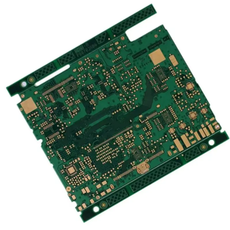
Component Placement: Power components like MOSFETs, inductors, and transformers must be placed for optimal thermal performance and minimal high-current loop areas. Control ICs should be isolated from noisy power sections.
Trace Routing: Power traces must be wide enough to handle the current without excessive heating. Use polygon pours for major power rails. Keep high-frequency switching loops as small as possible to reduce EMI.
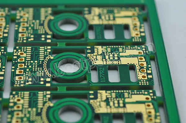
Thermal Management: The PCB itself is a heatsink. Incorporate thermal vias under high-power components to conduct heat to internal ground planes or dedicated thermal layers. Exposed pads on the bottom layer can interface with an external heatsink.
Via Selection: Use a combination of through-hole vias for high-current paths and blind/buried vias in complex, high-density boards to save space.
4. How to Choose a PCB Manufacturer
The most meticulous design can fail if poorly manufactured. Selecting the right PCB fabricator is critical. Key selection criteria include:
Technical Capability: Confirm the manufacturer can build to your specifications. This includes the number of layers, final board thickness, copper weight (3oz+), and controlled impedance tolerances.
Experience with Power Electronics: Choose a partner familiar with the challenges of power supply PCBs, such as thick copper and heavy copper balance to prevent warping.
Quality and Certifications: Look for certifications like ISO 9001, IATF 16949, and UL listing. A robust quality control process, including Automated Optical Inspection (AOI) and electrical testing, is mandatory.
DFM Feedback: A good manufacturer will perform a Design for Manufacturability (DFM) check and provide feedback to improve yield and reliability.
Supply Chain Stability: Ensure they have a resilient supply chain for raw materials to avoid production delays.
In conclusion, a high-performance Server Power Module PCB results from a holistic approach: a strategically planned stackup, disciplined use of design tools, careful layout adhering to power integrity principles, and a partnership with a capable and quality-focused manufacturer. Ignoring any of these aspects risks the entire server system's reliability.
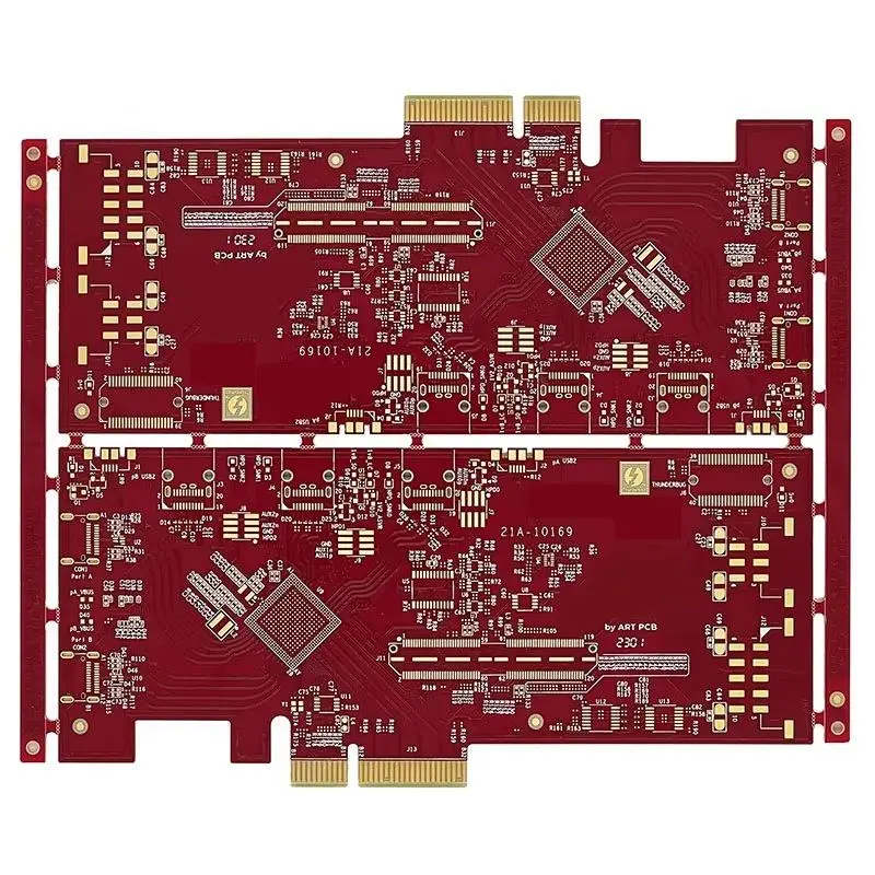
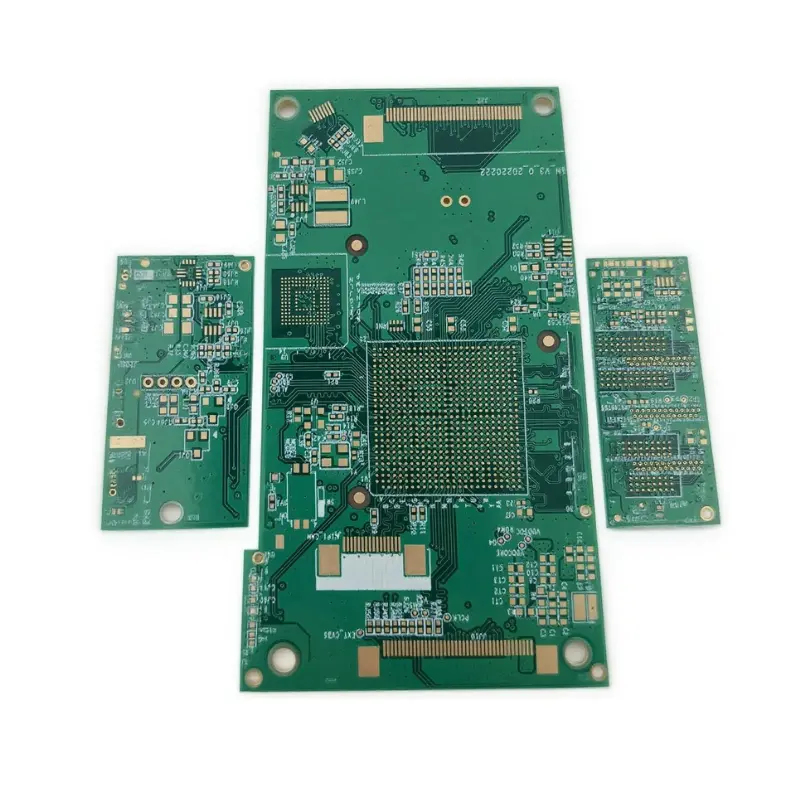
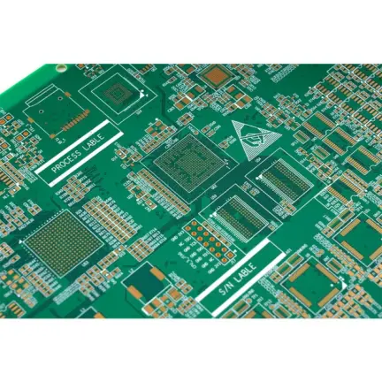
Model: Server Power Module PCB
Material: High TG FR4
Layer: 24Layers
Color: Green/White
Finished Thickness: 1.0mm
Copper Thickness: 2-3OZ
Surface Treatment: Immersion Gold
Min Trace: 8mil (0.2mm)
Min Space: 8mil (0.4mm)
Application: Power Module PWB
Certificate:ROSH. ISO9001. UL. ISO13485