Technical Overview of an Automotive-Grade HDI Rigid-Flex PCB for Prototype Development
The evolution of automotive electronics demands printed circuit boards (PCBs) that offer superior reliability, high density, and mechanical resilience. This technical article provides a detailed examination of the specifications for a high-performance Automotive-Grade High-Density Interconnect (HDI) Rigid-Flex PCB (R-FPCB), designed specifically for demanding prototype applications.
Core Design and Construction
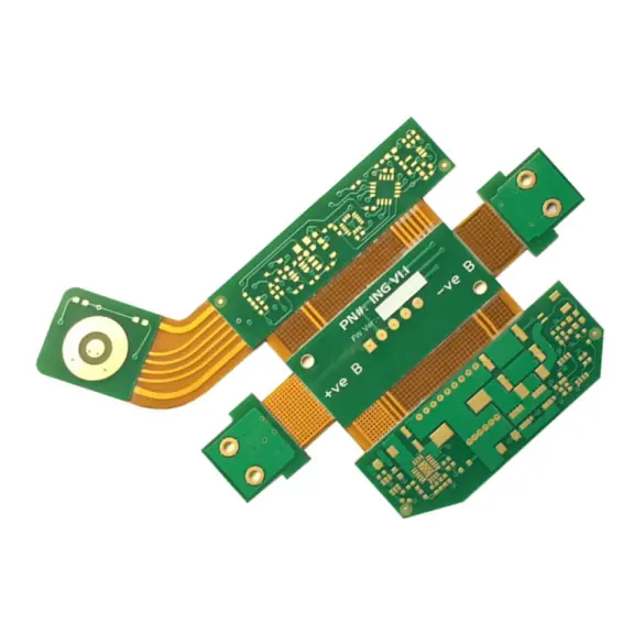
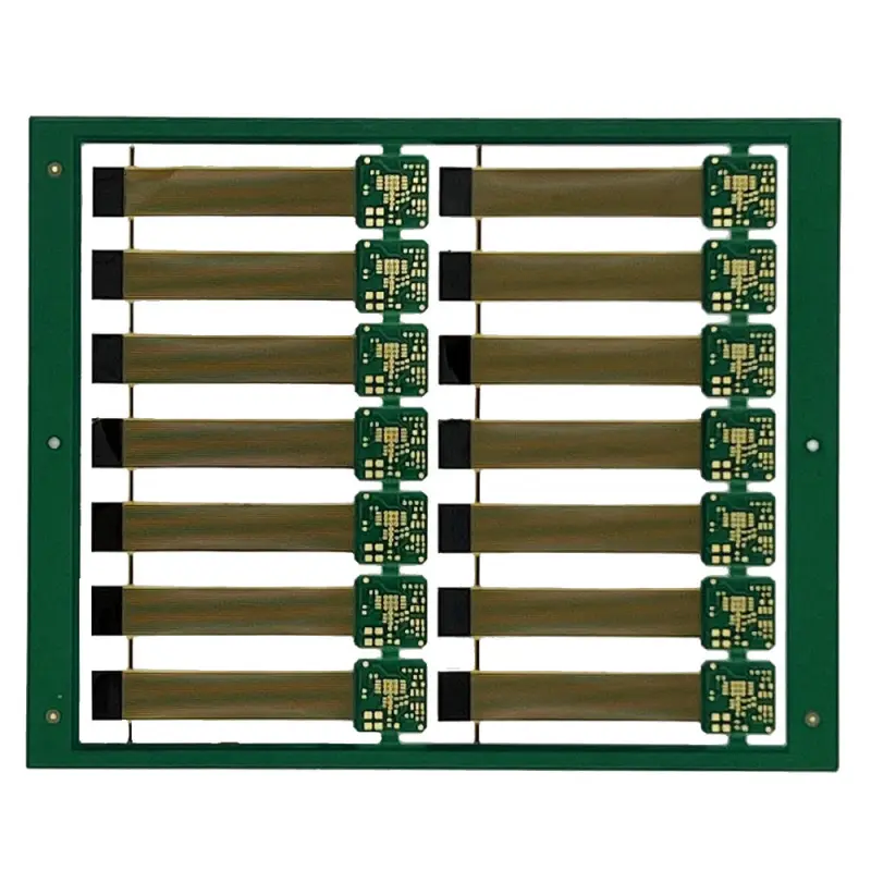
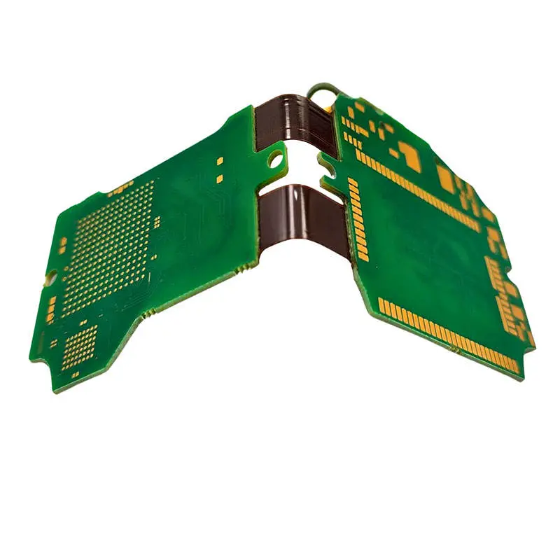
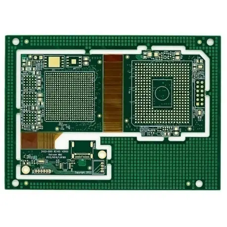
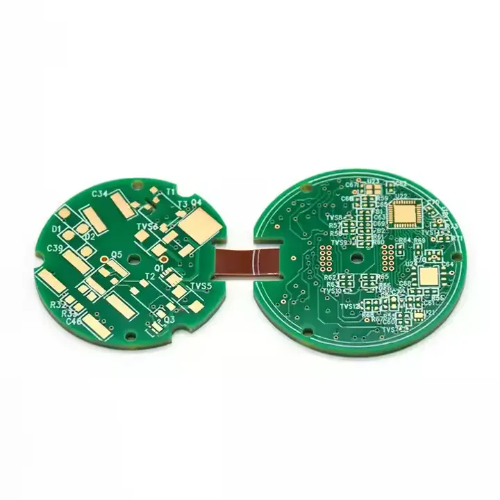
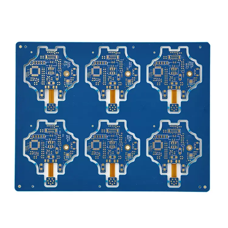
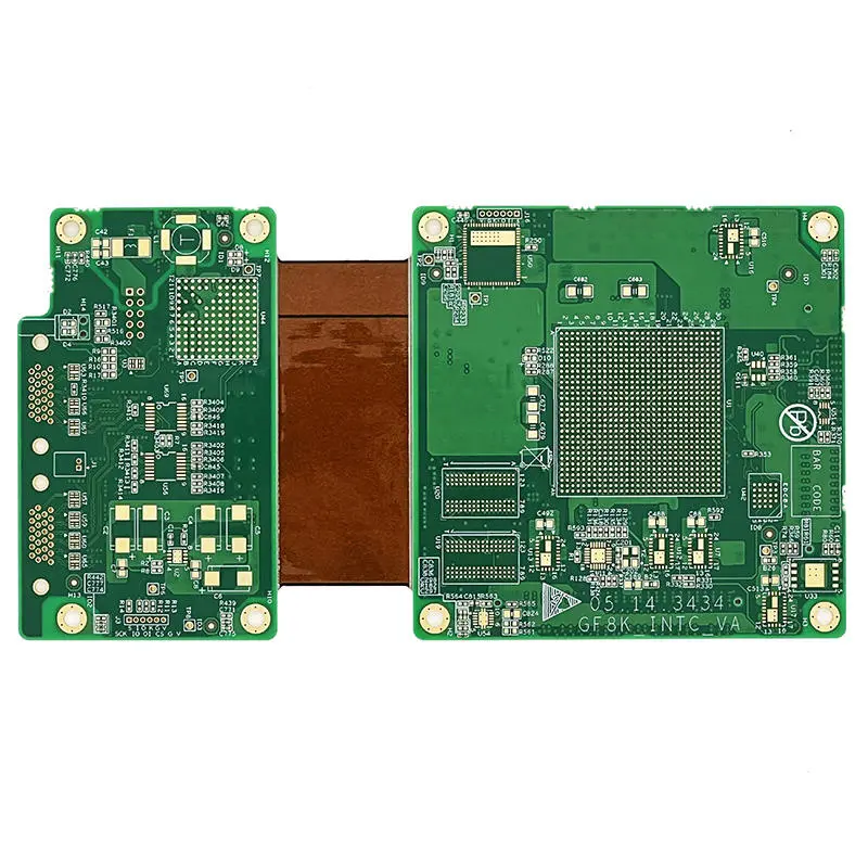
This board is classified as an HDI Rigid-Flex model, signifying its integration of rigid substrates for structural support and flexible segments for three-dimensional packaging. The designated layer stack-up of 1+2+1 describes a symmetrical construction featuring one rigid layer, two consecutive flexible polyimide layers, and a second rigid layer. This configuration is optimal for applications requiring repeated flexing or complex folding within a confined space, such as in-vehicle infotainment systems or sensor modules.
Material Composition and Key Physical Properties
"The selection of materials is critical for meeting automotive reliability standards.
1、Base Materials: The rigid sections are fabricated from FR-4, a robust and flame-retardant epoxy laminate. The flexible segments utilize Polyimide (PI), renowned for its excellent thermal stability, chemical resistance, and mechanical flexibility.
2、Finished Thickness: The final board has a controlled finished thickness of 1.2 mm, achieving a balance between mechanical strength and compactness.
3、Copper Thickness: A standard 1 oz/ft² (0.035 mm) copper thickness is used for the conductors, providing a good balance between current-carrying capacity and fine-line etching capabilities.
4、Solder Mask: The board is available with either Green or White solder mask, serving to protect the copper traces from oxidation and short circuits during soldering."
Critical Manufacturing and Finish Specifications
"Precision manufacturing is essential for the functionality of this HDI board.
1、Surface Treatment: The board undergoes an Electroless Nickel Immersion Gold (ENIG 2U"") surface finish. This process deposits a thin layer of gold (2 micro-inches) over a nickel barrier, ensuring a flat, oxidation-resistant surface ideal for fine-pitch components and providing excellent solderability and wire-bonding capability.
2、Minimum Trace/Space: The minimum line width and distance of 0.1/0.1 mm qualifies this as an HDI PCB. This fine feature size allows for a higher density of interconnections in a smaller area, which is crucial for advanced automotive electronics."
Primary Application
This PCB is engineered for Automotive Electronics Rigid-Flex PCB Prototype development. It serves as a critical platform for validating the design, functionality, and durability of electronic control units (ECUs), lighting systems, and other advanced driver-assistance systems (ADAS) components before volume production.
The combination of a robust 1+2+1 rigid-flex construction, automotive-qualified materials (FR-4+PI), a reliable ENIG finish, and HDI-level miniaturization makes this PCB model an excellent choice for engineers developing next-generation automotive electronic prototypes that require high reliability in challenging environments.
Model Identifier: Automotive PCB (HDI R-FPCB)
Base Material Composition: FR-4 (Rigid Section) + Polyimide (Flexible Section)
Layer Construction: 1+2+1 (1 Rigid Layer + 2 Flex Layers + 1 Rigid Layer)
Solder Mask Color: Green / White
Overall Finished Thickness: 1.2 mm
Copper Foil Thickness: 0.035 mm (1 oz/ft²)
Final Surface Finish: Electroless Nickel Immersion Gold (ENIG), 2µ" (Micron Inches) Gold Thickness
Minimum Feature Size: 0.1 mm line width / 0.1 mm spacing
Primary Application: Prototype development for automotive electronics utilizing rigid-flex PCB technology.

")
")