Technical Overview of Rigid-Flex PCB Prototype Manufacturing Specifications
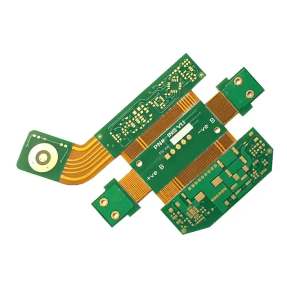
The adoption of rigid-flex PCB technology is critical for innovating modern digital products that demand high reliability in compact form factors. This article provides a detailed technical breakdown of the standard specifications for a rigid-flex PCB prototype, commonly used in the development of advanced digital devices.
Core Construction and Material Selection
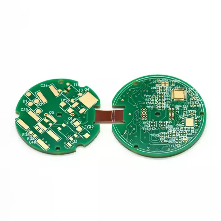
"The foundation of a reliable rigid-flex PCB lies in its hybrid construction.
1、Rigid Sections: These areas utilize FR-4, a glass-reinforced epoxy laminate known for its excellent mechanical strength, stability, and cost-effectiveness. The rigid boards provide a stable platform for mounting complex components.
2、Flexible Sections: These dynamic areas are built with Polyimide (PI) film. PI is selected for its exceptional thermal resistance, flexibility, and dielectric properties, allowing the board to withstand repeated bending during installation and operation."
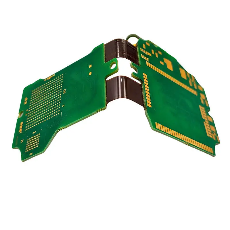
Layer Stack-up Architecture: The 2+2+2 Configuration
"common and effective configuration for prototypes is the 2+2+2 stack-up. This denotes:
1、Two conductive layers on the rigid FR-4 sections.
2、Two conductive layers within the central flexible polyimide core.
3、Another two conductive layers on the opposing rigid FR-4 sections."
This architecture provides an optimal balance of circuit complexity and flexibility, enabling sophisticated routing while maintaining the board's dynamic capabilities.
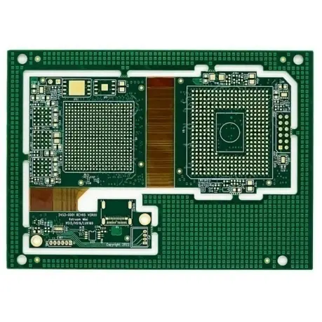
Critical Fabrication Parameters and Tolerances
"Precision in manufacturing is non-negotiable. The following specifications are paramount for ensuring signal integrity and structural reliability:
1、Finished Thickness: The rigid sections are fabricated to a thickness of 1.0mm, while the flexible polyimide core is maintained at a slender 0.15mm. This ensures durability in the rigid areas and maximum flexibility in the dynamic ones.
2、Copper Thickness: A standard 1 oz (0.035mm) copper weight is used for all layers, providing a solid foundation for current carrying capacity and controlled impedance.
3、Minimum Trace/Space: The design rules support a minimum trace width and spacing of 0.1mm / 0.1mm. This fine-line capability is essential for high-density interconnect (HDI) designs common in digital electronics.
4、Surface Finish: The board features an Immersion Gold (ENIG) surface treatment. This process deposits a thin layer of gold over a nickel barrier, offering a flat, solderable surface ideal for fine-pitch components and providing excellent oxidation resistance."
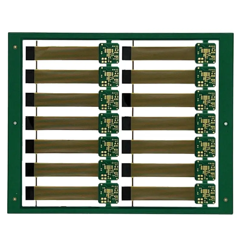
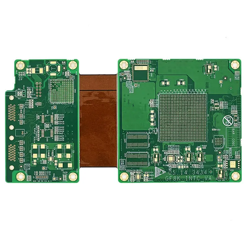
Application in Digital Product Development
This specific set of specifications is ideally suited for the prototype fabrication of digital rigid-flex PCBs. It provides engineers with a robust and predictable platform for testing form, fit, and function in devices such as smartphones, wearable technology, high-density cameras, and medical instruments, where space and weight are at a premium.
Understanding these fundamental manufacturing specifications is the first step in successfully leveraging rigid-flex technology. The detailed parameters—from the FR-4/PI material combination and 2+2+2 layer build-up to the precise 0.1mm trace tolerances and ENIG finish—define a capable and reliable prototype solution for pushing the boundaries of digital product design.
Product Category: Rigid-Flex PCB (R-FPCB)
Construction Material: FR-4 (Rigid) & Polyimide (Flexible)
Layer Stack-up: 2-Layer Rigid / 2-Layer Flexible / 2-Layer Rigid
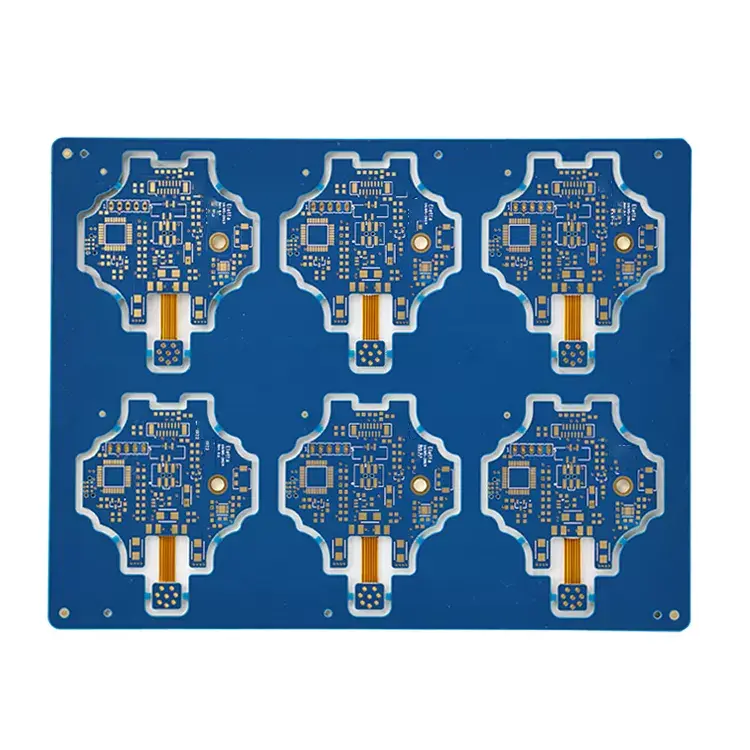
Solder Mask / Silkscreen: Green / White
Finished Board Thickness: 1.0mm (Rigid Core) + 0.15mm (Flexible PI)
Copper Weight (Thickness): 1 oz (0.035mm)
Surface Finish: Immersion Gold (ENIG)
Minimum Trace/Space: 0.1mm / 0.1mm
Target Application: Digital Product Rigid-Flex PCB Prototype Development