Technical Manufacturing Guide: Advanced Millimeter Wave Radar PCBA for 76-81GHz FMCW Applications
Millimeter wave radar technology represents the cutting edge of high-frequency sensing solutions, demanding precision manufacturing capabilities for optimal performance. This technical overview examines the manufacturing specifications and design considerations for a professional-grade 76-81GHz FMCW radar printed circuit board assembly (PCBA) utilizing Texas Instruments' advanced RF processing technology.
PCB Architecture and Material Selection
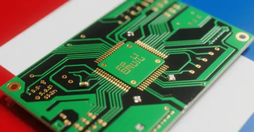
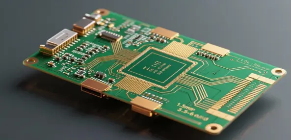
The foundation of high-frequency radar performance begins with appropriate layer stack-up and substrate materials. This design employs a 4-6 layer multilayer configuration, balancing routing complexity with signal integrity requirements. The substrate combines RO3003 high-frequency laminate with Isola 370HR prepreg, creating an optimal dielectric environment for millimeter wave transmission. This material selection provides consistent dielectric constant (Dk) and low loss tangent across the operational frequency band, critical for phase stability and minimal signal attenuation.
Surface Treatment and Copper Specifications
Immersion silver surface finish is specified for its excellent RF performance characteristics at millimeter wave frequencies. This finish maintains superior solderability while minimizing signal loss compared to alternative treatments. The standardized 1oz copper thickness (approximately 35μm) ensures consistent impedance control and thermal management throughout the PCB structure. Manufacturers should note that immersion silver requires controlled storage conditions to prevent oxidation prior to assembly.
Manufacturing and Testing Protocols
PCB fabrication includes comprehensive electrical testing to verify circuit continuity and isolation characteristics. The manufacturing process emphasizes tight impedance tolerance control (±10%) for critical RF transmission lines. While board-level testing is completed, PCBA-level functional testing is typically excluded from standard manufacturing scope, requiring customers to implement appropriate validation procedures post-assembly.
Component Integration and Application
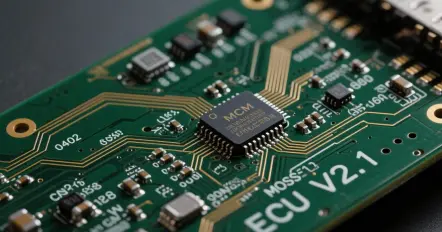
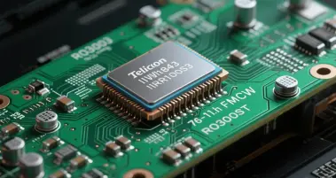
The design centers on Texas Instruments' IWR1843BOOST integrated circuit, a highly integrated CMOS solution for radar applications. This system-on-chip (SoC) combines RF front-end, analog baseband, and digital signal processing capabilities in a single package. The PCBA operates as a complete 76-81GHz FMCW (Frequency Modulated Continuous Wave) radar sensor, suitable for advanced automotive, industrial, and security applications requiring precise range, velocity, and angle detection capabilities.
Aesthetic and Identification Options
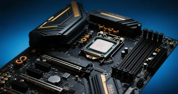
Multiple solder mask color options (green, black, white, red, blue) provide flexibility for different application environments and identification schemes. While color selection doesn't impact electrical performance, black and white masks often serve in automotive and high-reliability applications where thermal management and marking visibility are considerations.
Manufacturing Considerations
Successful production of millimeter wave radar PCBAs requires manufacturers with specific expertise in high-frequency materials and processes. Key considerations include controlled impedance manufacturing, precision solder paste deposition for RF components, and strict contamination control throughout the assembly process. The combination of advanced materials, sophisticated IC technology, and precision manufacturing makes this PCBA suitable for next-generation radar applications across multiple industries.
This millimeter wave radar PCBA represents a sophisticated integration of high-frequency PCB technology and advanced radar signal processing. The specified materials, layer structure, and component selection create a robust foundation for 76-81GHz FMCW radar implementations where performance reliability and signal integrity are paramount. Manufacturers implementing these specifications should maintain strict process controls to ensure consistent high-frequency performance across production volumes.
PCB Construction: 4-6 Layer Multilayer Architecture
Base Substrate: High-Frequency Laminated Material (RO3003 core with Isola 370HR)
Surface Finish: Immersion Silver (ENIG Alternative Not Specified)
Copper Weight: 1 oz/ft² (Standard Thickness)
Board Color Options: Green/Black/White/Red/Blue (Solder Mask)
PCB Electrical Test: Included (Board-Level)
Primary IC: Texas Instruments IWR1843BOOST Integrated Circuit
Functional Test Coverage: PCBA-Level Testing Excluded
Operational Frequency Band: 76–81 GHz FMCW (Frequency-Modulated Continuous Wave)
Functional Application: Millimeter-Wave Radar Sensing Solution

")