


Motor Drive & Inverter PCBA: Comprehensive Technical Guide & Industry Insights
Motor Drive & Inverter PCBA: The Core of Modern Motion Control Systems
As the "power brain" of motor control systems, Motor Drive & Inverter PCBA plays a pivotal role in converting electrical energy into precise mechanical motion. With the global surge in industrial automation, electric vehicles (EVs), and smart home technologies, the demand for high-performance, reliable Motor Drive & Inverter PCBA has skyrocketed. This comprehensive guide delves into the core technologies, design principles, application scenarios, and frequently asked questions about Motor Drive & Inverter PCBA, serving as an authoritative reference for engineers, procurement professionals, and technology enthusiasts.
Key Concepts: What is Motor Drive & Inverter PCBA?
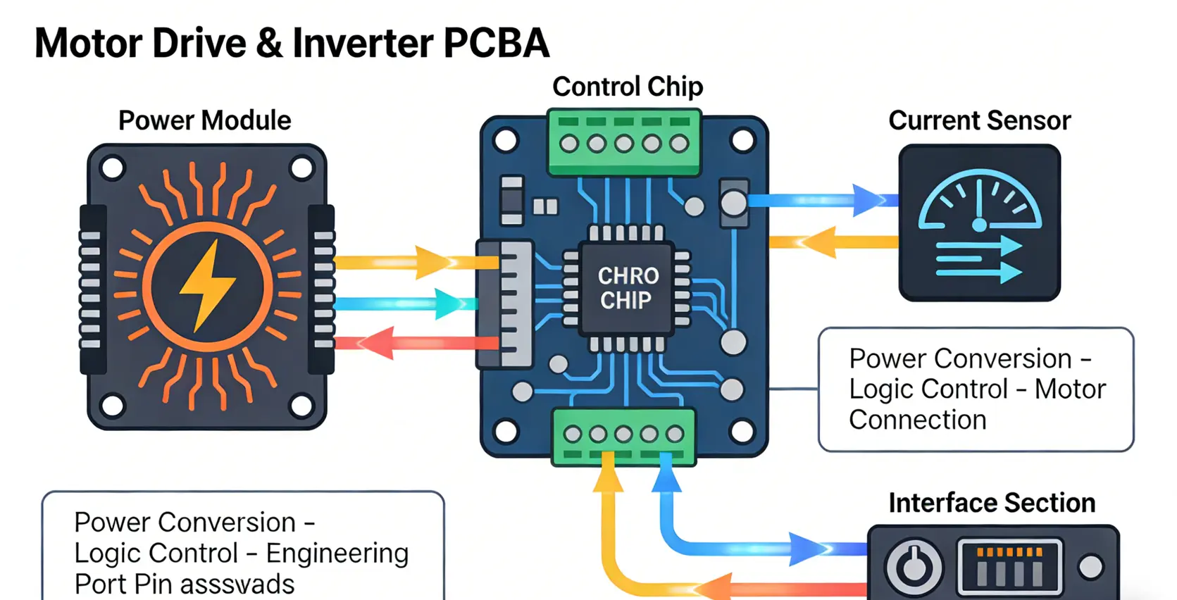
Motor Drive & Inverter PCBA refers to the printed circuit board assembly that integrates power conversion circuits, control logic, and protection mechanisms to drive various types of motors. The inverter module converts direct current (DC) to alternating current (AC) with adjustable frequency and voltage, while the drive module regulates motor torque, speed, and position through advanced algorithms. Together, they form the core control unit of motion systems, enabling efficient, stable, and precise motor operation.
Unlike standard PCBs, Motor Drive & Inverter PCBA must withstand high voltage, large current, and harsh operating environments, requiring specialized design considerations and high-reliability components. Common motor types compatible with these PCBs include Brushless DC (BLDC) motors, Permanent Magnet Synchronous Motors (PMSM), stepper motors, and AC induction motors.
Core Design Principles of Motor Drive & Inverter PCBA
The design of Motor Drive & Inverter PCBA is a systematic project that involves power topology selection, component matching, PCB layout, and thermal management. Below are the key design principles to ensure performance and reliability:
1. Power Topology Selection
The power topology determines the basic performance of the Motor Drive & Inverter PCBA. Common topologies include:
• Three-Phase Full Bridge Topology: Composed of 6 MOSFETs, widely used in BLDC and PMSM drives (e.g., EV powertrains, industrial servo systems) due to its ability to implement Space Vector Pulse Width Modulation (SVPWM) for smooth speed control.
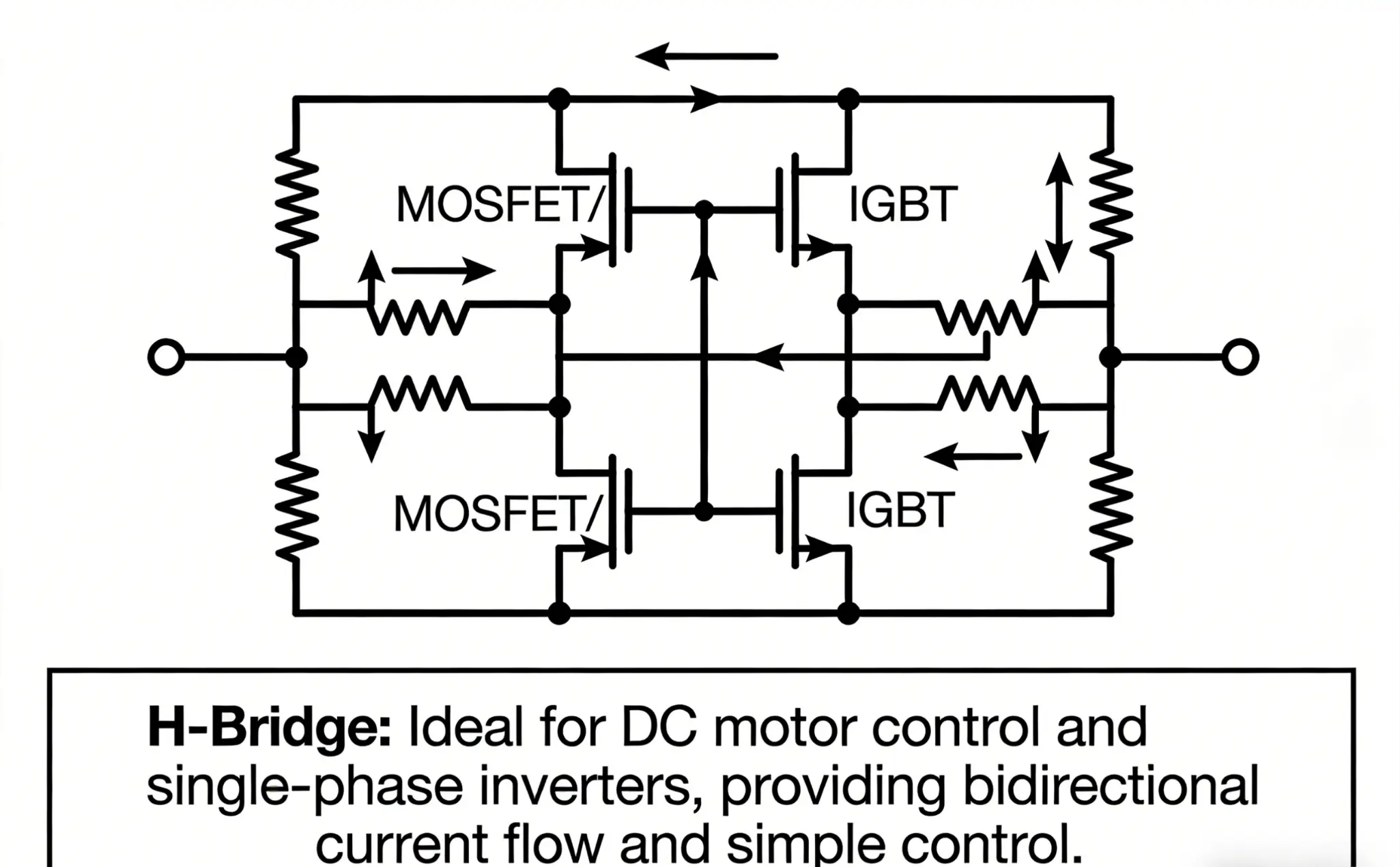
• H-Bridge Topology: Consists of 4 MOSFETs, suitable for brushed DC motors and small stepper motors, enabling four-quadrant operation (forward, reverse, acceleration, deceleration).
• Half-Bridge Topology: Used in low-power applications, offering cost advantages but limited to unidirectional operation.
With the development of wide-bandgap semiconductors, silicon carbide (SiC) and gallium nitride (GaN) MOSFETs are increasingly adopted in power topologies, enabling higher switching frequencies (up to 1MHz), higher efficiency (up to 98.5%), and smaller form factors compared to traditional IGBTs.
2. Key Component Selection
Component selection directly impacts the reliability and performance of Motor Drive & Inverter PCBA. Critical components include:
• Power Devices: SiC/GaN MOSFETs (for high-power, high-frequency applications) and IGBTs (for medium-power industrial applications). For example, 1200V SiC MOSFETs are used in 440V AC motor drives to improve efficiency and reduce heat generation.
• Gate Drivers: Specialized ICs (e.g., IR2104, IR2101S) that provide sufficient driving current to power devices, ensuring fast switching and preventing shoot-through. Isolated gate drivers are preferred for high-voltage applications to enhance safety.
• Current Sensors: Shunt resistors with differential amplifiers (e.g., INA240) or current transformers, used to monitor motor current for closed-loop control and overcurrent protection.
• Microcontrollers (MCUs): The "brain" of the PCBA, responsible for running control algorithms. High-performance MCUs (e.g., STM32G431) with built-in FOC hardware accelerators are ideal for complex motor control tasks.
3. PCB Layout & Routing Best Practices
PCB layout is critical for minimizing electromagnetic interference (EMI) and ensuring thermal stability in Motor Drive & Inverter PCBA. Key practices include:
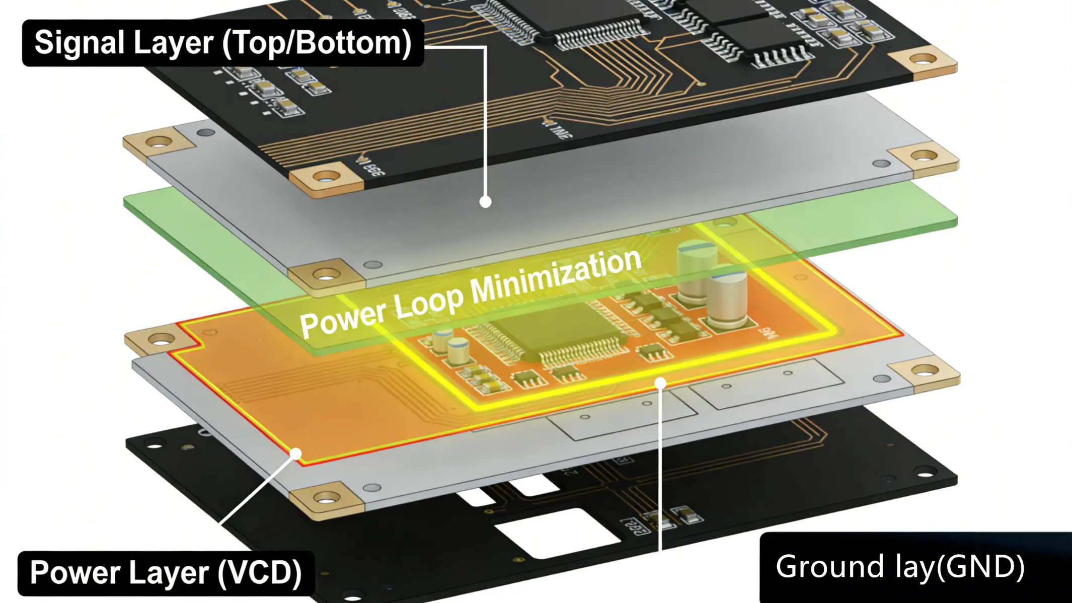
• Minimize Power Loop Area: The loop formed by the power device, motor, current sensor, and decoupling capacitor should be less than 4 cm² to reduce EMI and voltage spikes.
• Separate Analog and Digital Grounds: Use star grounding to isolate analog (current sensing, feedback) and digital (MCU, communication) ground planes, preventing digital noise from interfering with analog signals.
• High-Voltage and Low-Voltage Isolation: Maintain a safe distance (≥8mm for 48V systems) between high-voltage power traces and low-voltage control traces to avoid arcing.
• Four-Layer PCB Design: Recommended for high-power applications, with layers assigned as follows: Layer 1 (signal & gate drivers), Layer 2 (ground), Layer 3 (power), Layer 4 (signal return).
4. Thermal Management
Motor Drive & Inverter PCBA generates significant heat during operation, especially in high-power applications. Effective thermal management includes:
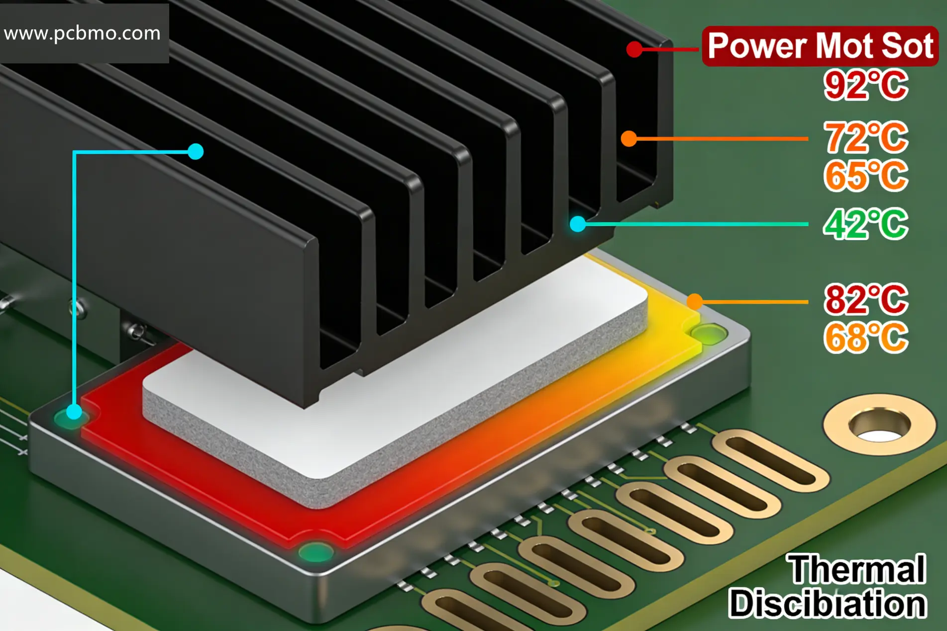
• Heat Sinks: Attached to power devices to dissipate heat, with thermal pads or thermal grease to improve heat transfer.
• Thermal Vias: Placed under power devices to conduct heat from the top layer to the ground plane.
• Component Placement: Avoid placing heat-sensitive components (e.g., MCUs, sensors) near power devices. Ensure adequate airflow around heat-generating components.
Applications of Motor Drive & Inverter PCBA Applications of Motor Drive & Inverter PCBA
Motor Drive & Inverter PCBA is widely used across various industries, driven by the trend of electrification and automation. Key application areas include:
1. Electric Vehicles (EVs) & E-Mobility
In EV powertrains, Motor Drive & Inverter PCBA converts DC power from the battery to AC power for the traction motor. High-power density (up to 15kW/L) and high efficiency are critical requirements here. For example, Nidec’s E-Axle system integrates a motor, inverter, and reducer, with the inverter PCBA using SiC MOSFETs to achieve high efficiency and compact design.
Other e-mobility applications include electric bicycles, e-scooters, and eVTOL (electric vertical takeoff and landing) vehicles, where lightweight and high-reliability Motor Drive & Inverter PCBA are essential.
2. Industrial Automation
In industrial settings, Motor Drive & Inverter PCBA is used in servo systems, CNC machines, AGV (Automated Guided Vehicle) robots, and conveyor belts. These applications require precise position control (up to 0.01mm accuracy) and fast response times (≤200ms for load changes). Siemens’ SINAMICS S210 series, compliant with IEC 61800-7 standards, is a benchmark for industrial Motor Drive & Inverter PCBA.
3. Smart Home & Consumer Electronics
Low-power Motor Drive & Inverter PCBA is used in smart home appliances such as air conditioners, washing machines, and refrigerators (BLDC motor drives for energy efficiency). Consumer electronics applications include drones (BLDC motor control for stable flight) and 3D printers (stepper motor drives for precise layer deposition).
4. Renewable Energy Systems
In wind turbines and solar tracking systems, Motor Drive & Inverter PCBA controls the orientation of wind turbine blades and solar panels to maximize energy capture. These PCBs must withstand harsh outdoor environments (-40℃ to 85℃) and have a long service life (over 20 years).
Industry Trends in Motor Drive & Inverter PCBA
The Motor Drive & Inverter PCBA industry is evolving rapidly, driven by technological advancements and market demand. Key trends include:
• Wide-Bandgap Semiconductor Adoption: SiC and GaN devices are replacing traditional IGBTs, enabling higher efficiency, smaller size, and lower cooling requirements. The global SiC power device market is expected to grow at a CAGR of 25% from 2025 to 2031.
• Integration & Miniaturization: "Drive-Motor Integration" (DMD) solutions, which combine the Motor Drive & Inverter PCBA with the motor and encoder, are becoming increasingly popular, reducing size by up to 60% and improving system reliability.
• Intelligentization: AI-powered Motor Drive & Inverter PCBA with predictive maintenance capabilities (e.g., Rockwell Automation’s PowerFlex 755TS) can monitor motor health and predict failures, extending maintenance cycles to 5 years.
• Wireless Connectivity: Integration of Wi-Fi 6/6E and 5G modules enables remote parameter configuration and firmware updates, reducing deployment and maintenance time by up to 80%.
• Conclusion
• Motor Drive & Inverter PCBA is the core component enabling efficient and precise motor control, with applications spanning industrial automation, EVs, smart homes, and renewable energy. Its design requires careful consideration of power topology, component selection, PCB layout, and thermal management. As wide-bandgap semiconductors and intelligent technologies continue to advance, Motor Drive & Inverter PCBA will become smaller, more efficient, and more intelligent, driving the next wave of innovation in motion control systems. This guide serves as a foundational resource for anyone involved in the design, procurement, or maintenance of Motor Drive & Inverter PCBA.
•
Frequently Asked Questions (FAQ) About Motor Drive & Inverter PCBA
Q1: What causes a Motor Drive & Inverter PCBA to fail immediately after power-on?
A1: Common causes include incorrect wiring (e.g., reversing input/output terminals), faulty current sensors (e.g., current transformers with abnormal output), or遗留 fault codes. First, check the wiring and press the reset button to clear residual faults. If the issue persists, inspect the current sensors and power devices for damage.
Q2: Can a 380V Motor Drive & Inverter PCBA be used to drive a 220V motor of the same power?
A2: Yes, it is feasible by adjusting parameters. Set the motor voltage parameter from 380V to 220V and limit the maximum output voltage of the inverter to 220V. Ensure the motor’s rated current matches the PCBA’s output current capacity.
Q3: How to improve the EMI performance of Motor Drive & Inverter PCBA?
A3: Key measures include minimizing the power loop area, using shielded cables for motor connections, adding EMI filters at the input terminal, and separating analog and digital ground planes. Using SiC/GaN devices with faster switching speeds also helps reduce EMI when paired with proper snubber circuits.
Q4: Is it necessary to apply conformal coating to Motor Drive & Inverter PCBA?
A4: It depends on the operating environment. Most PCBs come with factory-applied potting compound. Conformal coating is only recommended for harsh environments (high humidity, heavy dust) to prevent corrosion. If applied, ensure it is fully cured to avoid affecting heat dissipation. For standard industrial environments, conformal coating is not required.
Q5: Why does the motor run at full frequency but with low current when driven by a Motor Drive & Inverter PCBA?
A5: If measuring input current, low values are normal because the motor is not fully loaded. If measuring output current, low values (e.g., 15A for a 37kW motor) indicate the motor is underloaded. Check the load condition and ensure the motor parameters (e.g., rated voltage, current) are correctly configured in the PCBA.
Q6: What is the difference between FOC and V/F control modes for Motor Drive & Inverter PCBA?
A6: Field-Oriented Control (FOC) provides precise torque and speed control, especially at low speeds, making it suitable for servo systems and EVs. It requires motor parameter self-learning. V/F (Voltage/Frequency) control is simpler and more cost-effective, suitable for fans and pumps. Self-learning is optional for V/F mode but recommended to improve low-speed torque performance.
Substrate Material
The substrate material of Motor Drive & Inverter PCBA is selected based on power requirements and heat dissipation needs, with the following specifications:
• FR-4 (Standard grade, with Tg values of 130°C, 170°C, or 200°C, suitable for general power scenarios)
• Aluminum-based PCB: Designed for high-power heat dissipation, with thermal conductivity ≥ 1.5 W/m·K, effectively reducing component temperature rise
• Copper-clad ceramic substrate (Al₂O₃/AlN): Applied in ultra-high power applications, thermal conductivity ≥ 200 W/m·K, ensuring stable operation of high-power devices
Copper Thickness
Copper thickness directly affects current-carrying capacity and power loop resistance, with specifications as follows:
• Standard copper: 1 oz (35 μm) or 2 oz (70 μm), meeting the needs of general signal and low-power circuits
• Heavy copper: 3 oz–10 oz (105 μm–350 μm), specially used for high-current busbars to avoid excessive temperature rise caused by high current
• Plated copper thickness in holes: ≥ 25 μm, ensuring low resistance of power loops and reliable current transmission
PCB Layer Count
The number of PCB layers is optimized according to signal isolation and power distribution requirements:
• Layer count range: 2–20 layers, multi-layer structure helps realize effective isolation between different signals and optimize power distribution
• Design principle: Separating power layer and signal layer to reduce EMI (Electromagnetic Interference) and ensure stable operation of the drive system
Minimum Line Width & Spacing
Line width and spacing are designed based on signal type and current magnitude to ensure signal integrity and avoid short circuits:
• Signal lines: Minimum line width and spacing are 3 mil / 3 mil (0.075 mm / 0.075 mm), adapting to the transmission needs of high-frequency control signals
• Power lines: ≥ 50 mil (1.27 mm) for high-current paths; the specific width is adjusted according to current density, and the long-term operating current density should be ≤ 20 A/mm²
Minimum Hole Size
Hole size is determined by drilling process and component mounting requirements, ensuring reliable plating and connection:
• Mechanical drill hole: Minimum size ≥ 0.2 mm, suitable for conventional through-hole components
• Laser drill hole: Minimum size ≥ 0.1 mm, used for micro-vias in HDI (High-Density Interconnect) structures, improving PCB integration
• Through-hole aspect ratio: ≤ 10:1, ensuring uniform and reliable plating of hole walls and avoiding poor conductivity caused by insufficient plating thickness
Surface Finish
Surface finish affects solderability and oxidation resistance, with options selected according to application scenarios:
• HASL (Lead-free): RoHS compliant, cost-effective, suitable for low-power drive products
• ENIG (Electroless Nickel Immersion Gold): Excellent oxidation resistance and flat surface, suitable for high-precision soldering of fine-pitch components
• OSP (Organic Solderability Preservative): Eco-friendly, with good solderability, ideal for fine-pitch components and lead-free processing
• Immersion Silver/Immersion Tin: Balanced in solderability and cost, a practical option for medium-power drive PCBA
Component Mounting Technology
Adopt appropriate mounting technology according to component type and power level, ensuring connection reliability:
• SMT (Surface Mount Technology): Used for miniaturized components such as QFP, SOP, DFN, MOSFETs, and IGBTs, improving PCB integration
• THT (Through-Hole Technology): Applied to high-power connectors, terminal blocks, and heat sinks, ensuring high mechanical strength and reliable current transmission
• Mixed Mounting (SMT + THT): Mainstream solution for motor drive PCBA, combining the advantages of miniaturization and high reliability
Power Device Compatibility
PCBA design needs to be compatible with different types of power devices to meet various power requirements:
• IGBT module: Supports packages such as TO-247, TO-220, D²PAK, and FSBB series, with current rating 10 A–600 A and voltage rating 600 V–1700 V
• MOSFET: Compatible with low-voltage (≤ 100 V) and high-voltage (≥ 600 V) devices, adapting to SMD packages such as DFN and SO-8
• Gate driver IC: Supports high-isolation devices with isolation voltage ≥ 2500 Vrms, ensuring safe and reliable drive of power devices
Thermal Management Parameters
Effective thermal management ensures stable operation of PCBA under high-power conditions:
• Thermal resistance of substrate: ≤ 0.5 °C/W for aluminum-based PCB, ensuring efficient heat conduction
• Heat sink attachment: Thermal pad thermal resistance ≤ 0.2 °C/W, adopting screw-locked or adhesive bonding to ensure close contact between heat sink and components
• PCB thermal design: Arrange thermal vias (diameter ≥ 0.3 mm, pitch ≤ 1 mm) under power devices to quickly dissipate heat to the bottom layer of the PCB
Soldering Requirements
Strict soldering requirements ensure the reliability of solder joints and long-term operation of PCBA:
• Reflow Soldering: Peak temperature 245°C ± 5°C, using lead-free solder, and the soldering profile complies with IPC/JEDEC J-STD-020 standards
• Wave Soldering: Temperature 260°C ± 5°C, dwell time 3–5 s, suitable for soldering THT components
• Solder joint reliability: Pass AEC-Q006 vibration test and thermal cycle test (-40°C to 125°C, 1000 cycles), ensuring no solder joint failure under harsh conditions
Electrical Performance
Electrical performance parameters ensure the stability and safety of the drive system:
• Insulation resistance: ≥ 10¹⁰ Ω (measured at 500 VDC between adjacent layers), avoiding leakage current
• Dielectric strength: ≥ 20 kV/mm for high-voltage isolation layers, ensuring safe operation under high-voltage conditions
• EMI suppression: Adopt impedance control (50 Ω / 100 Ω for signal lines) and reasonable grounding design (star grounding, chassis grounding), complying with EN 55011 standards to reduce electromagnetic radiation
Environmental Reliability
PCBA needs to adapt to harsh industrial environments, with the following reliability requirements:
• Operating temperature range: -40°C to 125°C (industrial grade), adapting to extreme temperature environments
• Humidity resistance: Pass 85°C/85% RH, 1000 h damp heat test without electrical failure
• Corrosion resistance: Pass salt spray test (5% NaCl, 48 h, IEC 60068-2-11 standard), suitable for harsh environments such as coastal and chemical industries
Compliance Standards
PCBA manufacturing complies with international and industry standards to ensure product quality and safety:
• RoHS / REACH: Restrict the use of hazardous substances, meeting environmental protection requirements
• IPC-A-610: Comply with the acceptability standards for electronic assemblies, with Class 2 (commercial grade) or Class 3 (high-reliability grade) requirements
• UL 94 V-0: PCB substrate meets flame retardant grade V-0, reducing fire risks


