In the intricate ecosystem of modern automotive technology, the Engine Control Unit (ECU) PCBA stands as the unrivaled “brain” that governs the performance, efficiency, and safety of vehicle engines. Far more than a simple circuit board, this critical assembly—often referred to interchangeably as Automotive ECU PCB, Car ECU PCBA, or ECM PCBA (Engine Control Module)—integrates a sophisticated array of electronic components designed to process real-time data, execute precise commands, and adapt to dynamic driving conditions. From regulating fuel injection and ignition timing in internal combustion engines to coordinating power distribution in hybrid vehicles, the ECU circuit board assembly is the linchpin of automotive functionality, ensuring seamless communication between mechanical systems and electronic controls. As vehicles evolve toward greater electrification and connectivity, the design and performance of the ECU board have become increasingly pivotal, demanding rigorous engineering standards and cutting-edge component integration. In this comprehensive analysis, we delve into the core components of the Engine Control Unit (ECU) PCBA, exploring their individual functionalities, interdependencies, and the critical role they play in shaping the modern driving experience.

1. Microcontroller Unit (MCU): The Central Processing Hub of the ECU Board
At the heart of every Engine Control Unit (ECU) PCBA lies the Microcontroller Unit (MCU), the primary processing component that serves as the “decision-maker” for all engine-related operations. The MCU is not merely a passive component on the ECU board; it is a highly specialized integrated circuit (IC) programmed to interpret sensor data, execute control algorithms, and send output signals to actuators—all within milliseconds. For Automotive ECU PCB designs, the MCU must balance three key requirements: processing speed, power efficiency, and ruggedness. Modern MCUs used in Car ECU PCBA and ECM PCBA (Engine Control Module) are typically based on 32-bit architectures (such as ARM Cortex-M series) or specialized automotive-grade processors, capable of handling multiple tasks simultaneously, including real-time data acquisition, fuel mapping calculations, and emissions control logic.
One of the defining features of the MCU in an ECU PCB is its ability to operate reliably in extreme automotive environments. Unlike consumer electronics, which operate in controlled temperatures, the ECU board is exposed to wide temperature fluctuations (-40°C to 125°C), vibration, and electromagnetic interference (EMI) from other vehicle systems. As a result, MCUs selected for Engine Control Unit (ECU) PCBA are rigorously tested to meet automotive industry standards (e.g., AEC-Q100) for temperature resistance, voltage stability, and long-term durability. Additionally, the MCU’s memory configuration—including flash memory for storing firmware and RAM for temporary data processing—must be optimized to support fast boot times and uninterrupted operation, even during voltage dips or transient electrical events.
The performance of the MCU directly impacts the overall efficiency of the ECU circuit board assembly. For example, a high-performance MCU can process data from 20+ sensors (e.g., oxygen sensors, throttle position sensors, crankshaft position sensors) in parallel, adjusting fuel injection timing by microseconds to maximize combustion efficiency and minimize emissions. In hybrid and electric vehicles, the MCU in the ECM PCBA (Engine Control Module) also coordinates with battery management systems and electric motor controllers, requiring even greater processing power and communication bandwidth. As automotive technology advances, MCUs in modern ECU boards are increasingly integrating artificial intelligence (AI) and machine learning capabilities, enabling adaptive control strategies that learn from driving patterns to optimize performance over time.
2. Sensor Interface Circuits: Bridging Data Sources and the ECU PCB
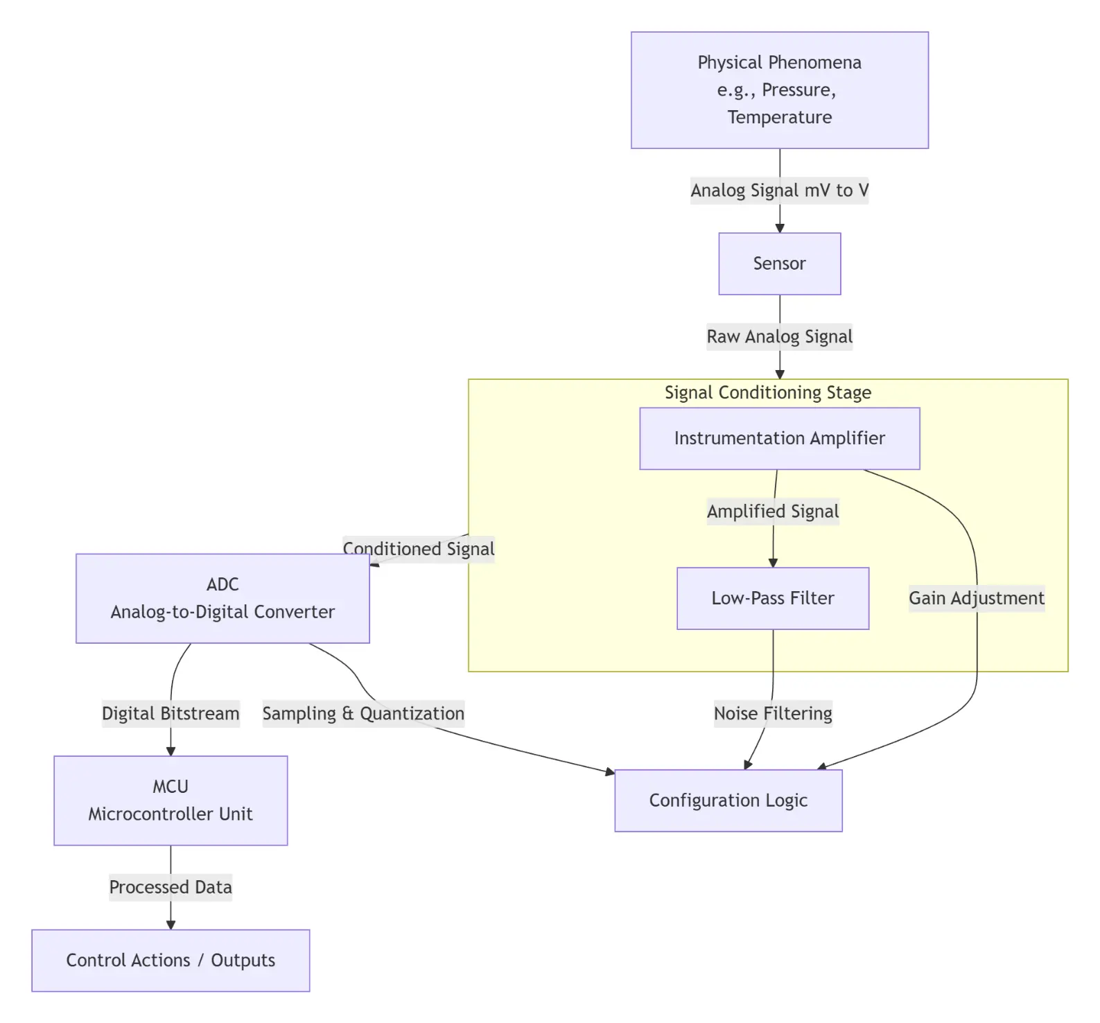
To make informed decisions, the Engine Control Unit (ECU) PCBA relies on a constant stream of data from dozens of sensors distributed throughout the vehicle. However, raw sensor signals—often weak, analog, or corrupted by noise—cannot be directly processed by the MCU. This is where sensor interface circuits, a critical component of the ECU PCB, come into play. These circuits act as translators and signal conditioners, converting raw sensor data into clean, digital signals that the MCU can interpret accurately. Whether in an Automotive ECU PCB for a heavy-duty truck or a Car ECU PCBA for a compact sedan, sensor interface circuits are designed to handle a wide range of sensor types, including analog sensors (e.g., temperature, pressure), digital sensors (e.g., Hall-effect speed sensors), and resistive sensors (e.g., throttle position sensors).
The design of sensor interface circuits on the ECU board is a delicate balance of precision and robustness. For analog sensors, the interface typically includes instrumentation amplifiers to boost weak signals, low-pass filters to eliminate high-frequency noise, and voltage regulators to stabilize power supplies. For example, an oxygen sensor in the exhaust system produces a millivolt-level signal that varies based on exhaust gas composition; the sensor interface circuit amplifies this signal to a range (e.g., 0-5V) compatible with the MCU’s analog-to-digital converter (ADC). For digital sensors, the interface includes logic level translators and pull-up/pull-down resistors to ensure compatibility with the MCU’s input/output (I/O) pins, while also providing protection against voltage spikes.
EMI immunity is another critical consideration for sensor interface circuits in the ECU circuit board assembly. Vehicle electrical systems generate significant electromagnetic noise from components like alternators, ignition coils, and power windows, which can corrupt sensor signals and lead to incorrect MCU decisions. To mitigate this, Automotive ECU PCB designs incorporate shielding layers, twisted-pair wiring for sensor connections, and EMC (Electromagnetic Compatibility) filters in the interface circuits. Additionally, many modern ECU PCBs use differential signaling for critical sensors (e.g., crankshaft position sensors), which inherently rejects common-mode noise, ensuring signal integrity even in harsh environments.
The reliability of sensor interface circuits directly impacts the safety and performance of the vehicle. A faulty interface circuit could cause the MCU to receive incorrect data—for example, misinterpreting a temperature sensor signal as indicating an overheated engine, leading to unnecessary fuel cutoffs or warning lights. As such, sensor interface circuits in Car ECU PCBA and ECM PCBA (Engine Control Module) undergo rigorous testing, including temperature cycling, humidity testing, and EMI susceptibility testing, to ensure they meet the strict reliability requirements of the automotive industry.
3. Actuator Driver Modules: Translating ECU Signals into Mechanical Action
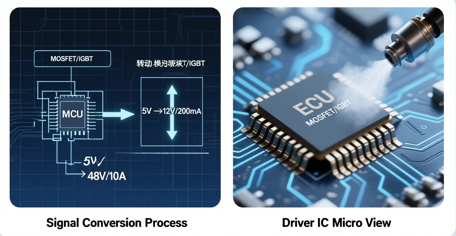
While sensor interface circuits gather data for the MCU, actuator driver modules are responsible for translating the MCU’s digital commands into physical action. Actuators are mechanical or electromechanical components that execute specific functions in the engine, such as fuel injection, ignition, valve control, and exhaust gas recirculation (EGR). However, the low-power signals from the MCU (typically 3.3V or 5V) are insufficient to drive these actuators, which often require high currents (amps) or high voltages (tens of volts). The actuator driver modules on the Engine Control Unit (ECU) PCBA solve this problem by amplifying the MCU’s control signals and providing the necessary power to operate the actuators.
The design of actuator driver modules varies depending on the type of actuator being controlled. For example, fuel injectors are typically driven by MOSFET (Metal-Oxide-Semiconductor Field-Effect Transistor) drivers, which can switch high currents quickly to control the duration of fuel injection. Ignition coils, on the other hand, require high-voltage drivers (often using IGBTs—Insulated-Gate Bipolar Transistors) to generate the 10,000+ volts needed to create a spark. In Automotive ECU PCB designs, these driver modules are often integrated into dedicated ICs (known as “actuator driver ICs”) that include built-in protection features such as overcurrent protection, short-circuit protection, and thermal shutdown.
Protection is a paramount concern for actuator driver modules in the ECU board. A short circuit in an actuator (e.g., a faulty fuel injector) could cause excessive current to flow through the driver module, leading to component failure or even damage to the MCU. To prevent this, driver modules in Car ECU PCBA and ECM PCBA (Engine Control Module) incorporate current-sensing resistors that monitor the current flowing to the actuator; if the current exceeds a safe threshold, the driver IC automatically shuts off the output, protecting both the ECU PCB and the actuator. Thermal protection is also critical, as driver modules generate heat during operation; many driver ICs include temperature sensors that trigger a shutdown if the module overheats, preventing permanent damage.
Another key consideration for actuator driver modules is response time. In engine control applications, timing is everything—for example, the fuel injection timing must be synchronized with the engine’s crankshaft position to within microseconds. As such, the driver modules on the ECU circuit board assembly are designed to switch on and off with minimal delay, ensuring that the actuator responds precisely to the MCU’s commands. This requires careful selection of components (e.g., fast-switching MOSFETs/IGBTs) and optimized PCB layout to minimize parasitic inductance and capacitance, which can slow down signal propagation.
4. Power Management Systems: Delivering Stable Power to the ECU PCB
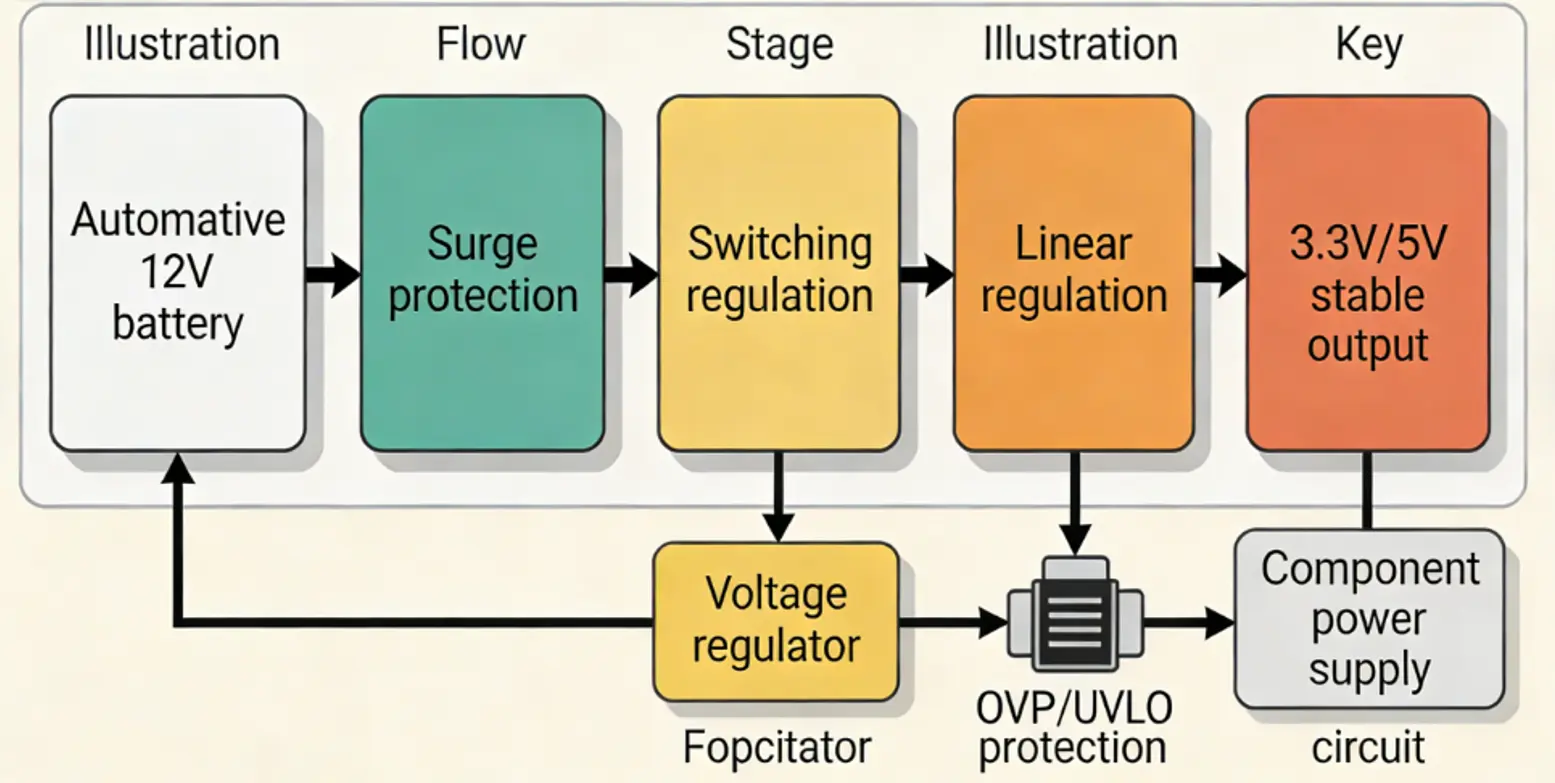
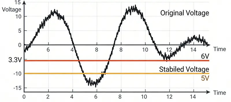
The Engine Control Unit (ECU) PCBA operates in a harsh electrical environment, where the vehicle’s power supply (typically a 12V lead-acid battery) is subject to significant fluctuations. When the engine starts, the battery voltage can drop to as low as 6V (due to the high current draw of the starter motor), while during charging, the alternator can push the voltage up to 14.8V or higher. Additionally, transient voltage spikes (e.g., from switching off high-current components like headlights) can reach hundreds of volts. To ensure stable and reliable operation of all components on the ECU board, the power management system is a critical component that regulates, filters, and protects the power supply.
At the core of the power management system in an Automotive ECU PCB is the voltage regulator. The primary function of the regulator is to convert the variable battery voltage into a stable DC voltage (typically 3.3V or 5V) that powers the MCU, sensor interfaces, and other low-power components. There are two main types of voltage regulators used in Car ECU PCBA and ECM PCBA (Engine Control Module): linear regulators and switching regulators. Linear regulators are simple, low-cost, and produce low noise, making them ideal for powering noise-sensitive components like the MCU’s analog circuits. However, they are inefficient at converting large voltage differences (e.g., 14V to 3.3V) and generate significant heat. Switching regulators, on the other hand, are highly efficient (85-95%) and generate less heat, making them suitable for high-power applications and situations where battery life is critical (e.g., hybrid vehicles). Many modern ECU PCBs use a combination of both: a switching regulator to convert the battery voltage to an intermediate voltage (e.g., 5V), and linear regulators to further refine the voltage to 3.3V for sensitive components.
In addition to voltage regulation, the power management system on the ECU PCB includes filtering components to eliminate noise from the power supply. Electrolytic capacitors and ceramic capacitors are used to smooth out voltage ripples, while ferrite beads suppress high-frequency noise. These filters are critical because noise in the power supply can corrupt sensor signals, interfere with MCU operations, and cause false triggers in actuator driver modules. For example, a voltage ripple in the power supply to the sensor interface circuit could be misinterpreted as a sensor signal, leading to incorrect fuel injection or ignition timing.
The power management system also includes protection features to safeguard the ECU circuit board assembly from electrical faults. Overvoltage protection (OVP) circuits monitor the input voltage and disconnect the ECU from the battery if the voltage exceeds a safe threshold (e.g., 18V), preventing damage to components like the MCU and driver ICs. Undervoltage lockout (UVLO) circuits ensure that the ECU does not operate at voltages too low to function properly (e.g., below 6V), which could cause erratic behavior or data corruption. Reverse polarity protection prevents damage if the battery is connected backwards, typically using a diode or a MOSFET that blocks current flow in the reverse direction.
Module Block Complete ECU Power Management Process
5. Communication Interfaces: Enabling Connectivity Within the Vehicle Network
Modern vehicles are equipped with a complex network of electronic control units (ECUs)—including the Engine Control Unit (ECU) PCBA, Transmission Control Unit (TCU), Body Control Module (BCM), and Infotainment System—all of which need to communicate with each other to ensure seamless vehicle operation. This communication is facilitated by dedicated communication interfaces on the ECU board, which enable data transfer between ECUs using standardized automotive communication protocols. The choice of communication interface depends on factors such as data transfer speed, cost, complexity, and the type of data being transmitted.
The most widely used communication protocol in automotive applications is CAN (Controller Area Network), which is used for high-speed, real-time communication between critical ECUs like the Engine Control Unit (ECU) PCBA and TCU. CAN is a serial bus protocol that allows multiple ECUs to communicate over a single pair of wires, reducing wiring complexity and cost. It supports data transfer speeds of up to 1 Mbps (CAN High) for critical applications and 125 kbps (CAN Low) for non-critical applications, and it includes built-in error detection and correction features to ensure data integrity. In an Automotive ECU PCB, the CAN interface typically consists of a CAN controller (integrated into the MCU or a separate IC) and a CAN transceiver, which converts the MCU’s digital signals into differential signals suitable for transmission over the CAN bus.
For lower-speed, less critical communication (e.g., between the ECU and the BCM for controlling dashboard indicators), the LIN (Local Interconnect Network) protocol is often used. LIN is a single-wire protocol that supports data transfer speeds of up to 20 kbps, making it simpler and cheaper than CAN. It is commonly used for peripheral devices that do not require real-time communication, such as power window controllers, seat adjusters, and climate control systems. The LIN interface on the ECU PCB includes a LIN controller and a LIN transceiver, which handles the physical layer of the communication.
In newer vehicles, especially those with advanced driver-assistance systems (ADAS) and electric powertrains, the Ethernet protocol is gaining traction for high-speed communication. Automotive Ethernet supports data transfer speeds of up to 10 Gbps, making it suitable for transmitting large amounts of data (e.g., video from cameras, sensor data from LiDAR systems) between ECUs. The Ethernet interface on the ECU circuit board assembly includes an Ethernet controller, a PHY (Physical Layer) IC, and a connector (e.g., RJ45 or automotive-specific connectors) for wired communication.
The communication interfaces on the Car ECU PCBA and ECM PCBA (Engine Control Module) are not only responsible for communicating with other ECUs but also for enabling diagnostics and software updates. Mechanics use diagnostic tools (e.g., OBD-II scanners) to connect to the ECU via the communication interface, allowing them to read fault codes, monitor sensor data, and perform system tests. Additionally, many modern ECUs support over-the-air (OTA) software updates, which are delivered via the vehicle’s infotainment system or a dedicated telematics module and transferred to the ECU via the communication interface. This enables manufacturers to fix software bugs, improve performance, and add new features without requiring the vehicle to be brought to a service center.
6. Memory Components: Storing Critical Data and Firmware
The Engine Control Unit (ECU) PCBA relies on various types of memory components to store the firmware that controls engine operations, temporary data generated during processing, and calibration data that optimizes performance for specific vehicle models. These memory components are integral to the functionality of the ECU board, as they determine the ECU’s ability to execute control algorithms, adapt to changing conditions, and retain critical information even when the vehicle is turned off.
The most important type of memory in an ECU PCB is non-volatile memory, which retains data even when power is disconnected. The primary non-volatile memory used in Automotive ECU PCBA and Car ECU PCBA is Flash memory, which stores the ECU’s firmware (the software that controls engine operations) and calibration data. Flash memory is ideal for this application because it is rewritable (allowing for software updates) and has a high endurance (able to withstand thousands of write cycles). The firmware stored in Flash memory includes control algorithms for fuel injection, ignition timing, emissions control, and other critical functions, while the calibration data includes maps and parameters that are optimized for the specific engine and vehicle model (e.g., fuel injection duration based on engine speed and load).
Another type of non-volatile memory used in some ECU boards is EEPROM (Electrically Erasable Programmable Read-Only Memory), which is used to store small amounts of data that need to be updated frequently, such as fault codes, mileage information, and adaptive learning data. EEPROM has a lower endurance than Flash memory but allows for individual byte-level erasure and writing, making it suitable for storing data that changes regularly.
Volatile memory, which loses data when power is disconnected, is used for temporary data processing. The main volatile memory in the Engine Control Unit (ECU) PCBA is RAM (Random Access Memory), which provides the MCU with a fast, temporary storage space for data being processed in real time. For example, when the MCU reads data from sensors, it stores the raw and processed data in RAM while executing control algorithms. RAM also stores intermediate results of calculations, such as fuel injection timing and ignition advance, before they are sent to the actuator driver modules. The size of the RAM in an ECU PCB depends on the complexity of the control algorithms and the number of sensors and actuators being managed; modern ECUs typically have between 64 KB and 1 MB of RAM, although high-performance ECUs for hybrid and electric vehicles may have more.
The memory components on the ECU circuit board assembly are subject to the same harsh environmental conditions as other components, including temperature fluctuations, vibration, and EMI. As a result, they must meet automotive industry standards for reliability and durability. For example, Flash memory and EEPROM used in ECM PCBA (Engine Control Module) are tested to ensure they retain data for extended periods (often 10+ years) at high temperatures, while RAM modules are designed to operate reliably at extreme temperatures and resist data corruption from voltage fluctuations.
7. Protection Circuits: Safeguarding the ECU PCB Against Faults and Environmental Hazards
Given the critical role of the Engine Control Unit (ECU) PCBA in vehicle operation, it is essential that the board is protected against a wide range of faults and environmental hazards. Protection circuits are designed to prevent damage to the ECU board and its components from electrical faults (e.g., short circuits, overvoltage), thermal stress (e.g., overheating), and mechanical stress (e.g., vibration). These circuits are integrated into the ECU PCB design to ensure maximum reliability and minimize the risk of ECU failure, which could lead to engine shutdown, reduced performance, or safety hazards.
Electrical protection is the most comprehensive type of protection on the ECU board. As discussed earlier, the power management system includes overvoltage protection, undervoltage lockout, and reverse polarity protection. However, additional electrical protection circuits are often included to safeguard specific components. For example, surge protection circuits (using metal-oxide varistors, or MOVs) are placed at the input of the ECU to absorb transient voltage spikes from the vehicle’s electrical system. ESD (Electrostatic Discharge) protection circuits are used to protect sensitive components like the MCU and sensor interfaces from electrostatic discharges, which can occur during maintenance or when the vehicle is exposed to static electricity. These circuits typically use TVS (Transient Voltage Suppressor) diodes that clamp voltage spikes to a safe level, preventing damage to the components.
Thermal protection circuits are designed to prevent the ECU PCB from overheating, which can degrade components and reduce their lifespan. The main sources of heat on the ECU board are the MCU, actuator driver modules, and power management components. Thermal protection is achieved through a combination of passive and active cooling. Passive cooling includes using heat sinks on high-power components, optimizing the PCB layout to maximize heat dissipation (e.g., using large copper planes), and selecting components with high operating temperature ratings. Active cooling, such as small fans or thermoelectric coolers, is sometimes used in high-performance ECUs or in vehicles with limited airflow around the ECU. Additionally, many components on the ECU circuit board assembly (e.g., driver ICs, voltage regulators) include built-in thermal shutdown features that disable the component if its temperature exceeds a safe threshold.
Mechanical protection is also important for the ECU PCB, as vehicles are subject to significant vibration and shock during operation. The PCB itself is designed to be mechanically robust, using thick copper layers for structural integrity and reinforced edges to resist bending. Components are mounted using SMT (Surface Mount Technology) or through-hole technology, depending on their size and weight, to ensure they remain securely attached to the board. Additionally, the ECU housing is often made of durable materials like aluminum or plastic, which provide physical protection against impact, dust, and moisture. Some ECUs also include conformal coating on the PCB, which is a thin layer of material (e.g., silicone, acrylic) that protects the components from moisture, dust, and corrosion.
8. Integration and Manufacturing: Ensuring Quality and Reliability of the ECU Circuit Board Assembly
The performance and reliability of the Engine Control Unit (ECU) PCBA depend not only on the quality of individual components but also on the integration and manufacturing processes used to assemble the board. Automotive ECU PCB manufacturing is subject to strict industry standards (e.g., IPC-A-610 for electronic assembly, ISO/TS 16949 for quality management) to ensure that the final product meets the rigorous requirements of the automotive industry. From PCB design and component selection to assembly and testing, every step of the manufacturing process is carefully controlled to minimize defects and maximize reliability.
PCB design is the first critical step in the integration process. The layout of the ECU board must be optimized to minimize signal interference, maximize heat dissipation, and ensure mechanical compatibility with the ECU housing. For example, high-power components (e.g., actuator driver modules, voltage regulators) are placed in areas with good airflow to facilitate heat dissipation, while sensitive analog components (e.g., sensor interfaces, ADCs) are separated from high-noise digital components (e.g., MCU, communication interfaces) to prevent EMI. The PCB also includes multiple ground planes to reduce ground loops and improve signal integrity, and trace widths are sized to handle the expected current flow without overheating.
Component selection is another key factor in ensuring the quality of the Car ECU PCBA and ECM PCBA (Engine Control Module). All components used in the ECU PCB must be automotive-grade, meaning they meet AEC-Q standards for reliability and performance in harsh environments. This includes components like MCUs, driver ICs, sensors, capacitors, and resistors, which are tested for temperature resistance, voltage stability, and long-term durability. Additionally, components are selected from reputable suppliers with a proven track record in the automotive industry, and rigorous incoming inspection is performed to ensure that components meet specifications.
The assembly process for the ECU circuit board assembly typically involves SMT (Surface Mount Technology), which is used to mount small, high-density components onto the PCB. SMT assembly is performed using automated equipment, including pick-and-place machines that place components onto the PCB with high precision, and reflow ovens that solder the components to the board. After assembly, the PCB undergoes a series of inspections to detect defects such as solder bridges, missing components, and poor solder joints. Visual inspections are performed using automated optical inspection (AOI) systems, which use cameras to detect defects, while electrical tests (e.g., in-circuit testing, functional testing) are performed to verify that the board operates correctly.
Functional testing is a critical part of the manufacturing process, as it ensures that the Engine Control Unit (ECU) PCBA performs all intended functions under real-world conditions. During functional testing, the ECU board is connected to a test bench that simulates the vehicle’s electrical system and sensors, allowing engineers to verify that the MCU correctly processes sensor data, sends accurate commands to actuators, and communicates with other ECUs. Environmental testing is also performed to ensure that the ECU PCB operates reliably in extreme temperatures, humidity, and vibration. This includes temperature cycling tests (exposing the board to extreme hot and cold temperatures), humidity tests (exposing the board to high humidity levels), and vibration tests (subjecting the board to the same vibration levels as a vehicle in operation).
Finally, the finished ECU circuit board assembly is integrated into the ECU housing, which provides physical protection and mechanical mounting points for the board. The housing is typically designed to be waterproof and dustproof (meeting IP67 or higher ratings) to protect the PCB from environmental hazards, and it includes connectors that allow the ECU to interface with the vehicle’s wiring harness. After final assembly, the complete ECU undergoes a final functional test to ensure that it meets all performance specifications, and it is labeled with a unique serial number for traceability.
Conclusion
The Engine Control Unit (ECU) PCBA is a marvel of automotive engineering, integrating a diverse array of core components—from the MCU and sensor interfaces to actuator drivers and communication modules—that work in perfect harmony to govern engine performance, efficiency, and safety. Whether referred to as Automotive ECU PCB, Car ECU PCBA, ECM PCBA (Engine Control Module), or simply ECU board, this critical assembly is the backbone of modern vehicle electronics, enabling the precise control and coordination of mechanical and electronic systems. As vehicles continue to evolve toward electrification, autonomy, and connectivity, the design and functionality of the ECU PCB will become even more sophisticated, requiring advances in component technology, integration, and manufacturing.
The key to the success of the ECU circuit board assembly lies in the careful selection of automotive-grade components, optimized PCB design, rigorous manufacturing processes, and comprehensive testing. Every component, from the smallest resistor to the most powerful MCU, plays a critical role in ensuring the reliability and performance of the ECU, and any defect or compromise in quality can have serious consequences for vehicle operation. By adhering to strict industry standards and leveraging cutting-edge technology, manufacturers are able to produce ECU PCBs that meet the demanding requirements of the automotive industry, providing drivers with a safe, efficient, and reliable driving experience.
In the future, the Engine Control Unit (ECU) PCBA will continue to be at the forefront of automotive innovation, integrating AI and machine learning capabilities to enable adaptive control strategies, supporting high-speed communication protocols for ADAS and autonomous driving, and becoming more compact and energy-efficient to meet the needs of electric and hybrid vehicles. As the “brain” of the vehicle, the ECU PCB will remain an indispensable component, driving the evolution of automotive technology and shaping the future of transportation.

 PCBA")
 PCBA")