
 PCBA")
 PCBA")
Battery Management System (BMS) PCBA: Design, Assembly, and Protection for Lithium Battery Applications
In the era of electrification—spanning electric vehicles (EVs), renewable energy storage, consumer electronics, and industrial power tools—the Battery Management System (BMS) has emerged as the central nervous system of any lithium-based battery pack. At the heart of every BMS lies its physical embodiment: the Battery Management System PCBA (Printed Circuit Board Assembly). This critical component integrates sensing, control, communication, and safety mechanisms into a compact, reliable platform. In this article, we delve into the architecture, manufacturing considerations, functional roles, and evolving trends of BMS PCBA, with special emphasis on BMS PCB Assembly, BMS Protection Board PCBA, and their indispensable role in modern Lithium Battery BMS PCBA applications.
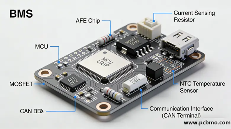
These functions are implemented through a combination of analog front-end (AFE) ICs, microcontrollers (MCUs), MOSFETs, shunt resistors, and isolation components—all mounted on a carefully designed PCB that undergoes rigorous BMS PCB Assembly processes.
Automated Optical Inspection (AOI) and X-ray inspection (for QFN thermal pads) are essential to ensure solder joint reliability—especially since field failures in a BMS Protection Board PCBA can have severe safety consequences.
Only after passing these tests is a Battery Management System PCBA deemed ready for integration into a battery module.
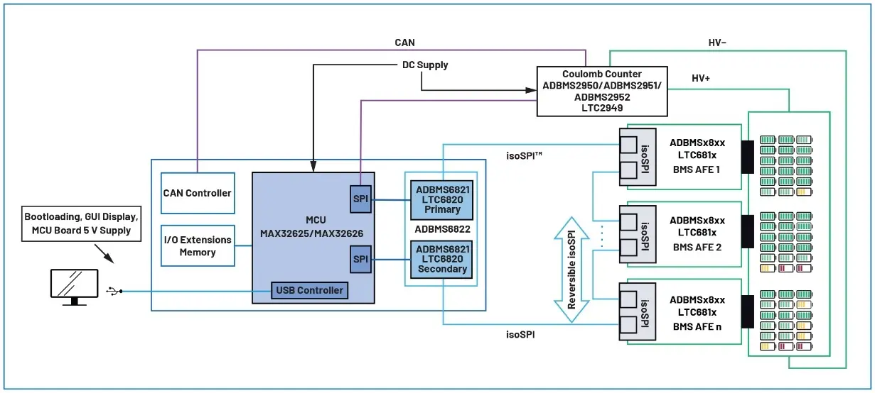
Moreover, wireless BMS (wBMS) architectures—pioneered by companies like Analog Devices—are eliminating copper interconnects between cells, reducing weight and improving reliability. However, even in wBMS, a centralized BMS Protection Board PCBA remains essential for master control and fail-safe operations.
I. PCB Design Parameters
Parameter Category
Typical Value / Requirement
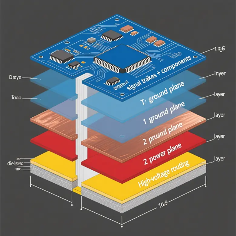
Number of Layers
2–8 layers (commonly 4 layers)
Base Material
FR-4 (high Tg for high-temperature environments), aluminum-core PCB (for high thermal dissipation)
Copper Thickness
1 oz – 2 oz (1 oz typical for signal layers; power layers may be thicker)
Minimum Trace Width/Spacing
≥0.15 mm (6 mil)
Hole Diameter Tolerance
±0.05 mm
Surface Finish
ENIG (Electroless Nickel Immersion Gold), HASL (lead-free or leaded), OSP
Impedance Control
Required for high-speed communication (e.g., CAN); e.g., 120Ω differential
II. Key Component Selection Parameters
Component Category
Key Specifications
Microcontroller (MCU)
Integrated ADC, CAN/LIN support, low-power modes, operating temperature range (-40°C to +125°C)
Cell Voltage Monitoring IC
Accuracy ±1–5 mV; channel count (typically 6–16 cells in series)
Current Sensing
Shunt resistor or Hall-effect sensor; accuracy ±0.5%–1%
Temperature Sensor
NTC/PTC thermistors; accuracy ±1°C
MOSFET Driver
Supports high-side/low-side drive; includes overcurrent protection
Communication Interfaces
CAN 2.0B, RS485, UART, I²C
Isolation Components
Digital isolators (e.g., ISO7741); isolation voltage ≥2.5 kVRMS
III. SMT (Surface Mount Technology) Manufacturing Process Parameters
Process Step
Technical Parameters
Placement Accuracy
±0.05 mm (for 0201, QFN, BGA packages)
Reflow Profile
Lead-free solder (e.g., SAC305): peak temperature 240–250°C, time above liquidus 30–60 seconds
AOI Inspection
Coverage ≥98%; capable of detecting missing components, misalignment, insufficient solder, etc.
X-Ray Inspection
Used for inspecting solder joints under BGA/QFN packages
Cleaning Process
Optional aqueous cleaning or no-clean (depending on flux type)
IV. Functional and Reliability Test Parameters
Test Item
Requirement
Cell Voltage Measurement Accuracy
±2 mV (typical)
Total Pack Voltage Error
≤±0.5%
Current Sensing Bandwidth
≥1 kHz (for dynamic response)
Insulation Resistance
≥100 MΩ (at 500 V DC)
Dielectric Withstand Test
1.5 kV AC for 1 minute (input-output, input-ground)
ESD Protection
±8 kV contact discharge, ±15 kV air discharge (per IEC 61000-4-2)
Operating Temperature Range
-40°C to +85°C (industrial grade) or -40°C to +125°C (automotive grade)
Vibration & Shock
Compliant with ISO 16750-3 (automotive) or IEC 60068-2 (general)
V. Compliance and Certification Requirements (Application-Dependent)
1、Automotive Grade: AEC-Q100 (ICs), ISO 26262 (functional safety, ASIL level), IATF 16949 (quality management)
2、Industrial / Energy Storage: UL 60730, IEC 62133, UN38.3 (transport safety)
3、Environmental Compliance: RoHS, REACH, halogen-free


